
|
|
LAMBORGHINI MIURA P400 |
| DRIVER'S HANDBOOK www.huskyclub.com/P400partslist.html |
S. Agata Bolognese (Bo)
DRIVER'S
HANDBOOK - Note
The technical concept behind the design and manufacture of the P400 Miura needs to be backed by the driver's good knowledge of and compliance with all the driving and maintenance instructions as outlined in the present handbook. If the exceptional performance of which this car is capable is to be achieved.
It is therefore advisable to consult this handbook not only when specific adjustment or maintenance operations have to be carried out on the vehicle, but also for the purpose of getting to know better the technical and operational data of the car.
For all tuning and maintenance work that the driver cannot carry out personally it is advisable to contact the Manufacturers or an Appointed Garage.
The use of original spare parts is a guarantee of satisfactory operation and long life.
Our Technical Service Department is entirely at your service for explanations and advise on all queries that you may wish to put to us.
CAPACITIES
Water (engine - radiator) - 15 liters - (Imp. gall. - 3.30 - U.S.A. gall. - 4.00)
Fuel - 88 liters - (Imp. gall. - 19.35 - U.S.A. gall. - 23.25)
Oil - 12.5 liters - (Imp. gall. - 2.75 - U.S.A. gall. - 3.30)
Fuel
Only Super or Premium petrol with an Octane N. 98/100 (RM) should be used. The fuel filler cap is accessible behind the right-hand grill of the bonnet. Lift the grill to open.
Oil
Check oil level with dipstick and top up if necessary, using exactly the same oil as already in the sump, and no other.
Water
Fill the water tank and bleed air from the cooling system unscrewing the bleed screw at the top left corner of the radiator; tighten bleed screw, top up tank, start engine and run it for ten seconds; bleed air once again and top up if necessary. When wishing to check the water level when engine is hot, the filler cap must be covered with a cloth, for protection, and released by 1/4 turn only, thus releasing internal pressure. If a lot of water is required, this should be added very slowly with the engine running at a slow idling speed.
IDENTIFICATION
Chassis identification N.:
LAMBORGHINI P400 MIURA
on the chassis front cross member.
Engine identification N.:
Stamped on the cylinder block between the cylinder heads.
The vehicle indentification numbers are also shown on a plate mounted on the chassis, near the front right wheel arch.
GENERAL DATA
Engine
Number of cylinders...................12
Cylinder arrangement................. 60° V
Bore.......................................... 82 mm
3-1/4" abt.
Stroke....................................... 62 mm
2-3/7" abt.
Cubic capacity........................... 3929 c.c.
Compression ratio..................... 1:9.5
Max. power at 7000 r.p.m......... 350 HP (DIN)
Fiscal power (for Italian road tax purposes) - 47
Vehicle
Wheelbase................................ 2504 mm
8'2-3/4" abt.
Overall length ........................... 4360 mm
14'4-1/10" abt.
Overall width............................ 1780 mm
5'10-1/4" abt.
Ground clearance (laden).......... 130mm
5-1/9" abt.
Overall height (laden)................ 1080 mm
3'5" abt.
Front track .............................. 1412 mm
Rear track ............................... 4'7-3/4" abt.
Turning circle............................ 11.20 m
3'8-1/7" abt.
Unladen weight ........................ 980 kg.
1,160 lbs
Laden weight including two....... 1250 kg.
people 2,755 lbs.
Standard (cuna formula) fuel.. 17 liters
consumption per 100Km (62 Imp. gall. 3.85
st. miles).............................. U.S.A. gall. 4.60
Normal oil consumption per 1.5 kg.
1000 km. ........................... 3,300 lbs
Max speed .............................. 300 k.P.H.
186 st. miles
Number of seats....................... 2
Tyre size (front and rear).......... 210 x 15
Electrical equipment ................ 12 Volts
Negative earth
RUNNING INSTRUCTIONS
Engine Oil Change
During initial running-in the oil should bre changed at the following intervals:
1st oil change at 1000 Km. (600 st.miles)
2nd oil change at 5000 Km. (3000 st.miles)
Check-list
Before starting up check the following items:
1. Water level in radiator tank
2. Engine oil level
3. Tyre pressure and wear
STARTING UP
Before starting the engine:
- make sure the gear lever is in neutral.
- insert ignition key and turn it clockwise to operate the starter.
- for easier starting the clutch pedal should be fully depressed. During the cold season the mixture can be enriched by depressing the accelerator pedal with pumping action.
Warning
Do not accelerate when cold, as the oil may not be reaching in sufficent quantity all points requiring lubrication and cause damage to the various parts.
Make sure that the oil pressure when hot and with engine idling at 900/1000 RPM is at least 1 to 1.5 atms.
If engine fails to start the cause may be one of the following:
- low battery charge
- faulty electrical equipment (dirty plugs, faulty
ignition coils, fouled distributor contacts or wrong breaker gaps.)
- short in wiring system
- clogged slow-running jets
- faulty fuel pump.
When driving
- Do not run the engine faster than the advised max. revs. (7500) in any gear.
- Check the oil pressure gauge frequently and switch off the engine if the pressure at max. revs., when oil is hot, drops below 5 atm.
- Do not depress the accelerator pedal fully until the oil has reached a temperature of 60° C. (140°F)
- Do not travel with the foot resting on the clutch pedal.
Winter season
If the temperature drops below 0°C (32°F) antifreeze should be used in the cooling system to prevent the water from freezing in the radiator and the engine during prolonged stops.
Summer ventilation
Air is drawn form the outside and directed into the car by means of the specially provided air outlets.
As both fresh air ducts are in fact ram air intakes, during slow town driving the circulation of fresh air can be increased with the electric blower. See switch.
Winter heating
Fresh air can be heated by passing it through a hot water matrix. For this purpose open the water tap located on the left hand side under the dashboard. Hot water will circulate in the matrix and warm the fresh air, which will be issued through the outlets in the car as before. Warm air can be directed to the windscreen when demist position is selected with the heater control lever. During slow running switch on the booster.
Seat adjustment
The seat position can be adjusted for distance operating the lever provided for this purpose under each seat.
Windscreen wiper
the twin speed wiper is operated by the switch on the transmission tunnel, controling also the windscreen washer.
Front bonnet - to open
The front bonnet is hinged at the front and therefore opens against the direction of travel. To open push the levers under the dashboard. Before starting the engine make sure the levers are in the locked position.
Rear or engine bonnet - to open
To open pull the two levers near the door strikers on the chassis. Before shutting the doors make sure the engine bonnet is properly locked.
Use of jack
The car can be lifted with the jack, which must be fitted into the jacking plates just ahead of the rear wheels arches. Before jacking make sure the handbrake is applied.
Washing the car
The car should be washed by experienced staff so as not to damage the paintwork. Do not wash the car in the sun or when the body panels are hot. Wash with plenty of clean water and dry with chamois-leather. Do not use synthetic detergents or soaps in the water.
Every so often the bodywork can be treated with car polish. After washing, the car should be driven slowly and the brakes applied lightly and repeatedly to dry the brakes.
Lubrication
Periodical lubrication
Every 500 Km. (300 st.miles)
1) Check oil level in the sump.
Every 5000 Km. 3,000 st.miles
1) Change engine oil and oil filter.
2) Lubricate with grease the half-shafts.
3) Lubricate with grease the steering box.
Every 20000 Km. (12,000 st.miles)
1) Lubricate with grease the wheels hubs.
ENGINE
The engine is pressure lubricated by a gear type oil pump driven by the crankshaft. The oil flows through the filter and into the crankcase. Oil level must always be within the max. and min. marks on the dipstick. The oil level should be measured with the car stationary on level ground. The oil filter element needs changing every 5000 Km (3,000 st.mile)
After changing the oil filter element check that there are no oil leaks from around the sealing face of the filter body. Oil pressure is controlled by a valve in the oil pump.
For good lubrication, the oil pressure should be within the pressures quoted in the table below:
Draining used oil
a) This operation should be carried out when hot. It is therefore advisable to run the engine for a few minutes to warm up the oil.
b) Open oil drain taps on engine sump and gearbox casing.
c) Remove filter and replace element.
Filling with fresh oil
The oil filler cap is on the off-side of the engine.
Recommended lubricants:
ENGINE BP HD motor oil SAE 50
Steering box BP Energrease L 21 M
Wheel bushes and
bearing BP Energrease LS 3
Transmission joint
grease nipples BP Energrease L 21 M
Once again it is stressed, never to use oil of different brand or type when topping up the engine oil.
MAINTENANCE
Periodical maintenance
Before using the car:
1) Check water level in radiator tank.
2) Check oil level in sump
3) Check tyre pressure
Every 500 Km. (300 st.miles)
4) Check water level in radiator tank
5) Check tyre pressure
Every 2500 Km. (1,500 st.miles)
6) Check battery electrolite level
7) Check clutch pedal free travel
8) Check fluid level in brake master cylinder reservoir
9) Check fluid level in clutch master cylinder reservoir
Every 5000 Km. (3,000 st.miles)
10) Check alternator belt tension
11) Check brake pedal free travel
12) Change wheels around and note tyre wear.
13) Check, clean and adjust distributor contacts
14) Check clutch free play
15) Adjust handbrake
Every 10000 Km. (6,000 st.miles)
17) Check wheel toe-in and camber angle
18) Check carburetter slow-running and adjust the linkage for total throttle valve aperture
19) Check disc pad wear
20) Replace spark plugs
21) clean air filters
Every 20000 Km. (12,000 st.miles)
22) Check clutch plate wear
23) Check valve clearances
24) Check steering free play
25) Clean out fuel filters and replace filter cartridges
ENGINE MAINTENANCE
The two cylinder heads are inclined at 60° giving the engine a V shaped configuration. The valves are directly operated by a camshaft for each line of valves, with interposed spring cups and pads for valve clearance adjustment.
Valve Timing
Inlet opens 32° B.T.D.C.
closes 76° A.B.D.C.
Exhaust opens 64° B.B.D.C.
closes 32° A.T.D.C.
Valve clearance inlet 0.25 mm (.0984")
(when cold) exhaust
Timing system
Engine timing:
The engine is correctly timed when:
a) Piston N. 1 of N/S cylinder block is at T.D.C. of compression stroke, and in this condition the point on the flywheel marked PMS N. 1 (T.D.C. N. 1) coincides with the arrow marked on the flywheel bell-housing.
b) The reference mark on each camshaft coincides with the corresponding mark on the front camshaft support.
Timing is independent on the two cylinder heads. On each side it is driven by the crankshaft via two reduction gears and double chain.
To adjust timing chain tension, slacken and remove nut from adjuster, remove cover plate and withdraw dowel: it is now possible to turn the adjusting cam in the required direction until the correct chain tension is obtained. Fit dowel into the seat where the holes coincide.
Attention: Over-tightening of the timing chains will cause damage and eventual failure to the reduction gear bearing and timing chains.
FUEL SYSTEM
Fuel Pump
Fuel is delivered from the tank to the carburettors by a 12 volts Bendix fuel pump of the " Red Head" type.
Fuel filters are fitted
1) At the end of the suction pipe in the tank.
2) in the pump
3) in the line between the pump and the carburettors.
Failure in delivery may be caused by
a) fault or inoperative pump.
b) clogged filters
c) leaks
CARBURETTORS
There are four (4) triple choke Weber 40 IDL - 3C carburettors, having the following settings:
- Choke.........................................30
- Centre resetting assembly.............4.5
- Running jet...................................125
- Slow-running jet...........................55
- Well.............................................F 26
- Air brake screw............................180
- Pump jet.......................................50
- Pump delivery...............................50
- Pump stroke.................................1/3
- Level............................................0
- Float.............................................25.5 grams
0.0562 lbs
- Air brake screw: open...................2 turns
Carburettor setting
Setting as supplied by the manufacturers should never be altered. In the event of uneven firing on deceleration, or at low speed under light load, clean the slow-running jets with air. These can easily be recognized as they are painted red.
Air filters
Each carburettor is provided with air filter. There is a single filter element on each bank of carburettors. The element is housed in a casing and is easily aaccessible by unscrewing the three retaining knobs, or releasing the 2 catches and removing the complete filter unit.
Maintenance
Every 5000 Km. (3,000 st.miles)
Clean the filter. Wash the filter with petrol and blow it out with compressed air directed from the inside to the outside. Before replacing the element it should be slightly wetted with engine oil.
Warning : never run the engine with the air filter removed. This not only to maintain good mixture adjustment but above all to prevent corrosive matter from getting to the cylinder bores and piston rings. The manufacturers do not accept any responsability when this warning is ignored.
Ignition
Ignition is by battery and two ignition distributors, one for each bank of cylinders, and two ignition coils. Each distributor is equipped with an automatic advance device.
Firing order
Cylinder 1 - 4 - 2 - 6 - 3 - 5 on each bank. Cylinder 1S (left N. 1) should have ignition when marking ASNI coincides with the arrow on the bell housing. When marking ADNI coincides with the arrow, ignition should be to the right hand cylinder N. 1.
Distributor
Type S 85 B 12 V with anticlockwise rotation
Stating timing Maximum timing
22° 22° + 19°
Distributor contact gap
With contacts fully open the maximum gap is .35 + .05 mm. (.01377" + .00196").
this gap can be adjusted when necessary by means of a locking screw and cam provided for this purpose. Contacts should always be clean; if necessary they can be cleaned with a very fine file.
MAINTENANCE AND ROUTINE CHECKS
Ignition timing
Right hand cylinder bank ignition distributor
a) Remove the distributor cap and chek that the contacts open with a gap of .35 + .05 mm. (.01377" + .00196").
IGNITION
If the timing has to be adjusted proceed as follows:
a) Slacken the nuts holding the distributor mounting flange to the cylinder head.
b) Turn distributor body clockwise to advance and anticlockwise to retard.
c) Tighten the three retianing nuts, making sure the distributor does not move during this operation.
Timing adjustment after dismantling
Remove the distributor cap and turn the spindle by hand until the rotor brush coincides with the contact for cylinder N. 1.
Check that the contacts are about to break.
If no adjustment was made in the driving sleeve, fit the distributor on its mounting, making sure that the fixing bolts are halfway in the mounting flange slotted holes. Replace the nuts but do not tighten.
Check timing as stated previously, turning the distibutor body clockwise or anticlockwise, and finally tighten the locknuts.
Spark plugs
Every 5000 Km. (3,000 st.miles) clean spark plugs and check plug gap (.35 mm); if the gap is greater it should be set to the correct value.
Every 10000 Km. (6,000 st.miles) spark plugs should be changed.
The recommended spark plugs are Bosch 250P, or any other of equivalent thermal rating and quality.
Cooling
The cooling system consists of water pump, piping , thermostat, filler tank, radiator, fan.
Water pump
Centrifugal, driven by crankshaft.
Thermostat
It is fitted into the circuit and set so as to allow the optimum water temperature into the engine at all times.
Filler tank (radiator tank)
This tank increases the capacity of the system, ensures water circulation within the cylinder heads and enables easier filling and topping up.
Radiator
Every 500 Km. (300 st.miles) check water level and top up, if necessary, with water (not limewater or hard water). If water consumption is too great, check tightness of filler cap on the tank.
The system is pressurized at .8 Kg. per sq.cm. If the water level must be checked when hot, the filler cap should be turned only by 1/4 of a turn to release internal pressure, using a piece of cloth as protection against escaping steam; after this the cap can be removed.
Check that excessive deposits do not foul the cooling system.
If necessary suitable solutions can be used to de-scale lime deposits, proceeding as follows:
- Fill the system with the right mixture of water and descaling agent.
- Run the eingine for ten minutes.
- Drain the system from the drain tap on the radiator.
- Fill the system with water only, and flush it with the engine running.
- Drain water and fill the system with pure water as recommended.
Water fans
Behind the radiators there are two independently operated motor driven cooling fans.
One is automatically operated by the thermostat, while the other can be switched on with the manual control switch on the panel.
Note
When traveling in town, heavy lane traffic, or at any time there is no ram air on the radiator, it is advisable to switch on the second fan immediately, to avoid reaching high temperatures, without waiting for the water temperature warning light.
Gear box
Transmission ratios:
1st speed 1 : 2.52
2nd speed 1: 1.735
3rd speed 1: 1.225
4th speed 1: 1
5th speed 1: 0.815
Reverse 1: 2.765
Clutch
Single dry plate, hydraulically operated. The clutch hydraulic system comprises a master cylinder - operated by the clutch pedal - a fluid reservoir and a slave cylinder acting on the thrust bearing via a relay linkage.
Clutch adjustment
- The pedal should have a free travel of 10-15 mm.
- Every 5000 Km.(3,000 st.miles) adjust the pedal free travel with the adjuster provided on the side of the clutch bell housing.
Differential
The crown and pinion normally used are the 11/45.
Final drive ratios gearbox - differential
Speed 11/45
1st 1 : 10.60
2nd 1 : 7.08
3rd 1 : 5.01
4th 1 : 4.08
5th 1 : 3.33
Reverse 1 : 11.32
Front suspension
Independent front wheel suspension with double wishbones, helical springs, telescopic shock absorbers and stabilizer bar.
Rear suspension
Independent rear wheel suspension with upper wishbone, inverted lower wishbone with tie rod, helical springs, telescopic hydraulic shock absorbers and stabilizer bar.
Every 20000 Km (12,000 st.miles) check the "silent block" bushes in the wishbones for wear and efficiency.
Every 25000 Km (15,000 st.miles) check the shock absorbers for efficiency.
Steering system
The steering box is of the rack and pinion type, requiring greasing every 10000 Km (6,000 st.mil.).
Suspension Alignment
Every 15000 Km.(9,000 st.miles) check front and rear wheel camber and toe-in, necessary for good roadholding and even wear of the tyres.
How to check wheel alignment
- Car under static load conditions, complete with fuel, oil, and water.
- Service tools required: camber measuring gauge and toe-in gauge.
Toe-in adjustment
a) Park the car with front wheels facing foward;
b) Check that the two reference marks on the rack housing and spindle are aligned;
c) Adjust the steering tie-rods until correct figure is obtained.
Camber - adjustment
a) Jack up the front of the car;
b) Remove the wheels;
c) Slacken the four nuts locating the end of the top swivel pin to the top arm and adjust as necessary along the slotted adjusting holes. Tighten the four nuts and check if adjustment was accurately carried out.
Brakes
The braking system consists of :
- Disc brakes on all four wheels with hydraulic control.
- Two independent hydraulic systems for front and rear wheels.
- Pressue increase valve on rear brake circuit.
- Mechanically operated handbrake on the rear wheels.
Hydraulics
Every 5000 Km.(3,000 st.miles) check fluid level in the two master cylinder reservoirs. The level must not be allowed to drop below the minimum mark. In the event of loss of fluid, top up the reservoirs and inspect the entire system for leaks.
Use Castrol Girling Brake Fluid Amber.
Remember never to use the aired fluid. Use sealed containers.
Maximum care must be paid when topping up the reservoir to make sure that drops of fluid do not come into contact with the paintwork, where it would cause irrevocable damage owing to its high corrosive quality.
Bleeding air from the circuit
This operation requires two people, a clear glass container fitted with a hook for hanging it to the brake caliper and a plastic hose with 6mm (1/4"abt.) internal diameter.
1) Check that brake fluid reservoirs are full. Remember that the fluid levels in the reservoirs should never drop by more than 1/4 and keep reservoirs well closed with plug provided.
2) Front calipers - insert one end of the plastic hose on to the caliper bleed screw and the other end into the glass container. Depress the brake pedal a few times keeping it fully depresed at the end of the last stroke. Slacken bleed screw and let out fluid mixed with air. Tighten bleed screw and allow brake pedal to return slowly to its normal position. Repeat the above proceedure several times if necessary, until the fluid coming out of the plastic hose is free from air bubbles.
3) Carry out this operation on the rear wheels.
4) After bleeding the brakes, check the brake fluid level and top up if necessary.
5) Check that the circuit does not leak anywhere and drive for a few miles using the brakes several times.
6) Repeat once again the brake bleeding operation as above.
Brake pads
The recommended brake pads are:
- Front brakes - FREN-DO FD 312
- Rear brakes - FREN-DO FD 312
They should be replaced when reduced to less than 4 mm. in thickness.
It is advisable to replace all brake pads at the same time.
Note
If pad wear is not even, check the surface and axial alignment of the brake discs (this operation should be carried out by an appointed garage).
In the event of uneven braking distribution, the system should be bleed once more exercising maximum care.
If this does not fully rectify the fault, check pad wear conditions and also the tightness rubber seals and slave cylinder sealing rings (all seal replacements must be carried out by an appointed garage).
Wheels
The wheels are dynamically balanced by special balancing weights. Every now and then check that the balancing weights are in there place.Unbalanced wheels produce uneven tyre wear but also severe fouling of the steering gear and seriously impair the stability of the car.
Every 20000 Km (12,000 st.miles) dismantle, clean and repack with grease the wheel hub bearings.
Tyres
Tyres pressures.
For good performance, comfortable ride and safe traveling the tyre pressure should be as shown in the table below: Pirelli 210 - 15 cinturato HS
The right pressure gives the best use of the whole tread with even and
more limited wear. Excessive pressure reduces ride comfort, gives extra
wear of the tread in the centre of the tyre and consequently reduces
tyre life.
Insufficient pressure causes the tyre to overheat which is dangerous as bits of tyre may become detached and fly off.
On top of this, the wrong tyre pressure affects the stability and roadholding of the vehicle. It is recommended to drive reasonably slowly with new tyres for 800 Km. (500 st.miles) as this also affects the stability of the car.
Every 5000 Km. (3,000 st.miles) change over the tyres diagonally.
This manual is in its original form! NO corrections have been
made! No errors corrected or spelling corrected or punctuation
corrected.
Most likely i have introduced new errors. Will somebody check this word for word against their manual please? thanks
http://www.huskyclub.com/P400partslist.html
The technical concept behind the design and manufacture of the P400 Miura needs to be backed by the driver's good knowledge of and compliance with all the driving and maintenance instructions as outlined in the present handbook. If the exceptional performance of which this car is capable is to be achieved.
It is therefore advisable to consult this handbook not only when specific adjustment or maintenance operations have to be carried out on the vehicle, but also for the purpose of getting to know better the technical and operational data of the car.
For all tuning and maintenance work that the driver cannot carry out personally it is advisable to contact the Manufacturers or an Appointed Garage.
The use of original spare parts is a guarantee of satisfactory operation and long life.
Our Technical Service Department is entirely at your service for explanations and advise on all queries that you may wish to put to us.
CAPACITIES
Water (engine - radiator) - 15 liters - (Imp. gall. - 3.30 - U.S.A. gall. - 4.00)
Fuel - 88 liters - (Imp. gall. - 19.35 - U.S.A. gall. - 23.25)
Oil - 12.5 liters - (Imp. gall. - 2.75 - U.S.A. gall. - 3.30)
Fuel
Only Super or Premium petrol with an Octane N. 98/100 (RM) should be used. The fuel filler cap is accessible behind the right-hand grill of the bonnet. Lift the grill to open.
Oil
Check oil level with dipstick and top up if necessary, using exactly the same oil as already in the sump, and no other.
Water
Fill the water tank and bleed air from the cooling system unscrewing the bleed screw at the top left corner of the radiator; tighten bleed screw, top up tank, start engine and run it for ten seconds; bleed air once again and top up if necessary. When wishing to check the water level when engine is hot, the filler cap must be covered with a cloth, for protection, and released by 1/4 turn only, thus releasing internal pressure. If a lot of water is required, this should be added very slowly with the engine running at a slow idling speed.
IDENTIFICATION
Chassis identification N.:
LAMBORGHINI P400 MIURA
on the chassis front cross member.
Engine identification N.:
Stamped on the cylinder block between the cylinder heads.
The vehicle indentification numbers are also shown on a plate mounted on the chassis, near the front right wheel arch.
GENERAL DATA
Engine
Number of cylinders...................12
Cylinder arrangement................. 60° V
Bore.......................................... 82 mm
3-1/4" abt.
Stroke....................................... 62 mm
2-3/7" abt.
Cubic capacity........................... 3929 c.c.
Compression ratio..................... 1:9.5
Max. power at 7000 r.p.m......... 350 HP (DIN)
Fiscal power (for Italian road tax purposes) - 47
Vehicle
Wheelbase................................ 2504 mm
8'2-3/4" abt.
Overall length ........................... 4360 mm
14'4-1/10" abt.
Overall width............................ 1780 mm
5'10-1/4" abt.
Ground clearance (laden).......... 130mm
5-1/9" abt.
Overall height (laden)................ 1080 mm
3'5" abt.
Front track .............................. 1412 mm
Rear track ............................... 4'7-3/4" abt.
Turning circle............................ 11.20 m
3'8-1/7" abt.
Unladen weight ........................ 980 kg.
1,160 lbs
Laden weight including two....... 1250 kg.
people 2,755 lbs.
Standard (cuna formula) fuel.. 17 liters
consumption per 100Km (62 Imp. gall. 3.85
st. miles).............................. U.S.A. gall. 4.60
Normal oil consumption per 1.5 kg.
1000 km. ........................... 3,300 lbs
Max speed .............................. 300 k.P.H.
186 st. miles
Number of seats....................... 2
Tyre size (front and rear).......... 210 x 15
Electrical equipment ................ 12 Volts
Negative earth
RUNNING INSTRUCTIONS
Engine Oil Change
During initial running-in the oil should bre changed at the following intervals:
1st oil change at 1000 Km. (600 st.miles)
2nd oil change at 5000 Km. (3000 st.miles)
Check-list
Before starting up check the following items:
1. Water level in radiator tank
2. Engine oil level
3. Tyre pressure and wear
STARTING UP
Before starting the engine:
- make sure the gear lever is in neutral.
- insert ignition key and turn it clockwise to operate the starter.
- for easier starting the clutch pedal should be fully depressed. During the cold season the mixture can be enriched by depressing the accelerator pedal with pumping action.
Warning
Do not accelerate when cold, as the oil may not be reaching in sufficent quantity all points requiring lubrication and cause damage to the various parts.
Make sure that the oil pressure when hot and with engine idling at 900/1000 RPM is at least 1 to 1.5 atms.
If engine fails to start the cause may be one of the following:
- low battery charge
- faulty electrical equipment (dirty plugs, faulty
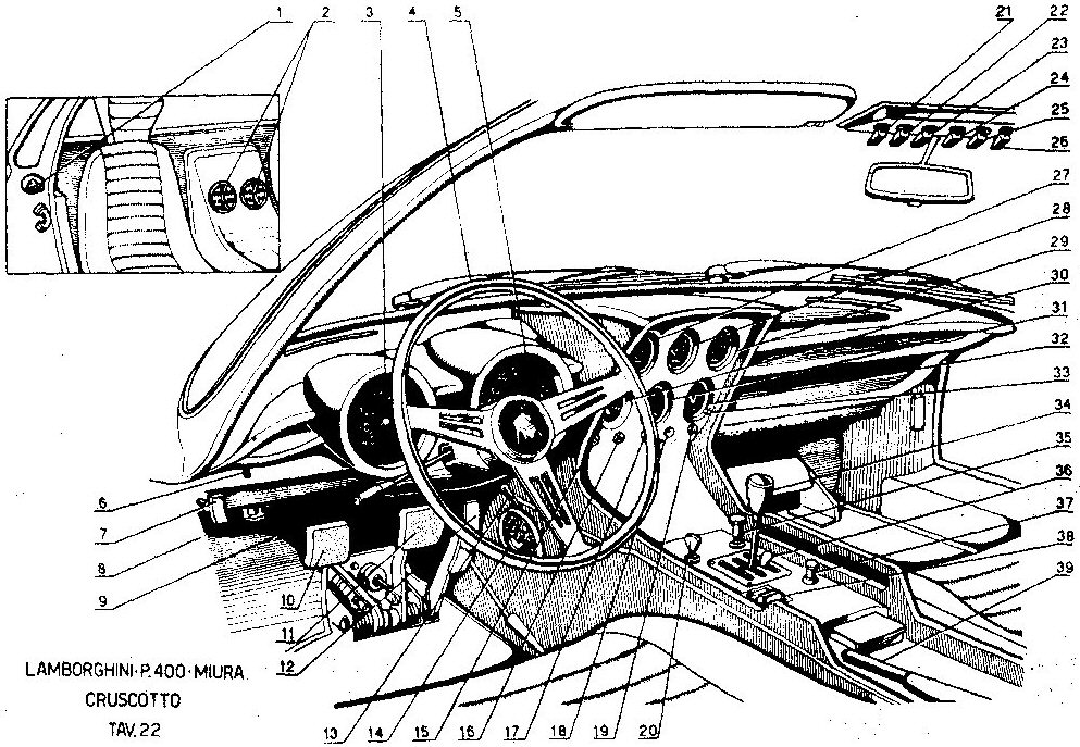
| LAMBORGHINI P 400 MIURA INTERNAL LAYOUT AND CONTROLS 1 REAR BONNET CATCHES 2 FRESH AIR OUTLETS 3 SPEEDOMETER 4 STEERING WHEEL 5 TACHOMETER 6 ODOMETER ZERO CONTROL 7 FRONT BONNET CATCHES 8 HEATER UNIT WATER VALVE 9 DIRECTIONAL INDICATOR LIGHT DIPPER FLASH SWITCH 10 CLUTCH PEDAL 11 BRAKE PEDAL 12 ACCELERATOR PEDAL 13 SCREEN DEMISTER VALVE 14 HEATER AIR OUTLET 15 POSTION LIGHTS 16 HIGH BEAM LIGHT 17 SECONDARY WATER RADIATOR |
18 ALTERNATOR WARNING LIGHT 19 FOG LIGHT WARNING LIGHT 20 IGNITION SWITCH 21 LIGHT SWITCH 22 SECONDARY RADIATOR FAN SWITCH 23 FOG LIGHT SWITCH 24 INTERIOR HEATER BLOWER SWITCH 25 PANEL LIGHT SWITCH 26 INTERIOR LIGHT SWITCH 27 WATER TEMPERATURE 28 OIL TEMPERATURE 29 OIL PRESSURE 30 FUEL LEVEL 31 AMPMETER 32 CLOCK 33 CLOCK SETTING SWITCH 34 GEAR LEVER 35 WINDSCREEN WIPER & WASHER SWITCH 36 RESERVE GEAR LOCK 37 CIGAR LIGHTER 38 HEADLIGHT RAISING SWITCH 39 HANDBRAKE LEVER |
 www.huskyclub.com/P400partslist.html |
- short in wiring system
- clogged slow-running jets
- faulty fuel pump.
When driving
- Do not run the engine faster than the advised max. revs. (7500) in any gear.
- Check the oil pressure gauge frequently and switch off the engine if the pressure at max. revs., when oil is hot, drops below 5 atm.
- Do not depress the accelerator pedal fully until the oil has reached a temperature of 60° C. (140°F)
- Do not travel with the foot resting on the clutch pedal.
Winter season
If the temperature drops below 0°C (32°F) antifreeze should be used in the cooling system to prevent the water from freezing in the radiator and the engine during prolonged stops.
Summer ventilation
Air is drawn form the outside and directed into the car by means of the specially provided air outlets.
As both fresh air ducts are in fact ram air intakes, during slow town driving the circulation of fresh air can be increased with the electric blower. See switch.
Winter heating
Fresh air can be heated by passing it through a hot water matrix. For this purpose open the water tap located on the left hand side under the dashboard. Hot water will circulate in the matrix and warm the fresh air, which will be issued through the outlets in the car as before. Warm air can be directed to the windscreen when demist position is selected with the heater control lever. During slow running switch on the booster.
Seat adjustment
The seat position can be adjusted for distance operating the lever provided for this purpose under each seat.
Windscreen wiper
the twin speed wiper is operated by the switch on the transmission tunnel, controling also the windscreen washer.
Front bonnet - to open
The front bonnet is hinged at the front and therefore opens against the direction of travel. To open push the levers under the dashboard. Before starting the engine make sure the levers are in the locked position.
Rear or engine bonnet - to open
To open pull the two levers near the door strikers on the chassis. Before shutting the doors make sure the engine bonnet is properly locked.
Use of jack
The car can be lifted with the jack, which must be fitted into the jacking plates just ahead of the rear wheels arches. Before jacking make sure the handbrake is applied.
Washing the car
The car should be washed by experienced staff so as not to damage the paintwork. Do not wash the car in the sun or when the body panels are hot. Wash with plenty of clean water and dry with chamois-leather. Do not use synthetic detergents or soaps in the water.
Every so often the bodywork can be treated with car polish. After washing, the car should be driven slowly and the brakes applied lightly and repeatedly to dry the brakes.
Lubrication
Periodical lubrication
Every 500 Km. (300 st.miles)
1) Check oil level in the sump.
Every 5000 Km. 3,000 st.miles
1) Change engine oil and oil filter.
2) Lubricate with grease the half-shafts.
3) Lubricate with grease the steering box.
Every 20000 Km. (12,000 st.miles)
1) Lubricate with grease the wheels hubs.
ENGINE
The engine is pressure lubricated by a gear type oil pump driven by the crankshaft. The oil flows through the filter and into the crankcase. Oil level must always be within the max. and min. marks on the dipstick. The oil level should be measured with the car stationary on level ground. The oil filter element needs changing every 5000 Km (3,000 st.mile)
After changing the oil filter element check that there are no oil leaks from around the sealing face of the filter body. Oil pressure is controlled by a valve in the oil pump.
For good lubrication, the oil pressure should be within the pressures quoted in the table below:
| Pressure (Atm.) |
Pressure (Atm.) |
|
| ENGINE REVS | Max |
Min |
| 6500 | 8-9 |
6-7 |
| 1000 | 1.5-2 |
Draining used oil
a) This operation should be carried out when hot. It is therefore advisable to run the engine for a few minutes to warm up the oil.
b) Open oil drain taps on engine sump and gearbox casing.
c) Remove filter and replace element.
Filling with fresh oil
The oil filler cap is on the off-side of the engine.
Recommended lubricants:
ENGINE BP HD motor oil SAE 50
Steering box BP Energrease L 21 M
Wheel bushes and
bearing BP Energrease LS 3
Transmission joint
grease nipples BP Energrease L 21 M
Once again it is stressed, never to use oil of different brand or type when topping up the engine oil.
MAINTENANCE
Periodical maintenance
Before using the car:
1) Check water level in radiator tank.
2) Check oil level in sump
3) Check tyre pressure
Every 500 Km. (300 st.miles)
4) Check water level in radiator tank
5) Check tyre pressure
Every 2500 Km. (1,500 st.miles)
6) Check battery electrolite level
7) Check clutch pedal free travel
8) Check fluid level in brake master cylinder reservoir
9) Check fluid level in clutch master cylinder reservoir
Every 5000 Km. (3,000 st.miles)
10) Check alternator belt tension
11) Check brake pedal free travel
12) Change wheels around and note tyre wear.
13) Check, clean and adjust distributor contacts
14) Check clutch free play
15) Adjust handbrake
Every 10000 Km. (6,000 st.miles)
17) Check wheel toe-in and camber angle
18) Check carburetter slow-running and adjust the linkage for total throttle valve aperture
19) Check disc pad wear
20) Replace spark plugs
21) clean air filters
Every 20000 Km. (12,000 st.miles)
22) Check clutch plate wear
23) Check valve clearances
24) Check steering free play
25) Clean out fuel filters and replace filter cartridges
ENGINE MAINTENANCE
The two cylinder heads are inclined at 60° giving the engine a V shaped configuration. The valves are directly operated by a camshaft for each line of valves, with interposed spring cups and pads for valve clearance adjustment.
Valve Timing
Inlet opens 32° B.T.D.C.
closes 76° A.B.D.C.
Exhaust opens 64° B.B.D.C.
closes 32° A.T.D.C.
Valve clearance inlet 0.25 mm (.0984")
(when cold) exhaust
Timing system
Engine timing:
The engine is correctly timed when:
a) Piston N. 1 of N/S cylinder block is at T.D.C. of compression stroke, and in this condition the point on the flywheel marked PMS N. 1 (T.D.C. N. 1) coincides with the arrow marked on the flywheel bell-housing.
b) The reference mark on each camshaft coincides with the corresponding mark on the front camshaft support.
Timing is independent on the two cylinder heads. On each side it is driven by the crankshaft via two reduction gears and double chain.
To adjust timing chain tension, slacken and remove nut from adjuster, remove cover plate and withdraw dowel: it is now possible to turn the adjusting cam in the required direction until the correct chain tension is obtained. Fit dowel into the seat where the holes coincide.
Attention: Over-tightening of the timing chains will cause damage and eventual failure to the reduction gear bearing and timing chains.
FUEL SYSTEM
Fuel Pump
Fuel is delivered from the tank to the carburettors by a 12 volts Bendix fuel pump of the " Red Head" type.
Fuel filters are fitted
1) At the end of the suction pipe in the tank.
2) in the pump
3) in the line between the pump and the carburettors.
Failure in delivery may be caused by
a) fault or inoperative pump.
b) clogged filters
c) leaks
CARBURETTORS
There are four (4) triple choke Weber 40 IDL - 3C carburettors, having the following settings:
- Choke.........................................30
- Centre resetting assembly.............4.5
- Running jet...................................125
- Slow-running jet...........................55
- Well.............................................F 26
- Air brake screw............................180
- Pump jet.......................................50
- Pump delivery...............................50
- Pump stroke.................................1/3
- Level............................................0
- Float.............................................25.5 grams
0.0562 lbs
- Air brake screw: open...................2 turns
Carburettor setting
Setting as supplied by the manufacturers should never be altered. In the event of uneven firing on deceleration, or at low speed under light load, clean the slow-running jets with air. These can easily be recognized as they are painted red.
Air filters
Each carburettor is provided with air filter. There is a single filter element on each bank of carburettors. The element is housed in a casing and is easily aaccessible by unscrewing the three retaining knobs, or releasing the 2 catches and removing the complete filter unit.
Maintenance
Every 5000 Km. (3,000 st.miles)
Clean the filter. Wash the filter with petrol and blow it out with compressed air directed from the inside to the outside. Before replacing the element it should be slightly wetted with engine oil.
Warning : never run the engine with the air filter removed. This not only to maintain good mixture adjustment but above all to prevent corrosive matter from getting to the cylinder bores and piston rings. The manufacturers do not accept any responsability when this warning is ignored.
Ignition
Ignition is by battery and two ignition distributors, one for each bank of cylinders, and two ignition coils. Each distributor is equipped with an automatic advance device.
Firing order
Cylinder 1 - 4 - 2 - 6 - 3 - 5 on each bank. Cylinder 1S (left N. 1) should have ignition when marking ASNI coincides with the arrow on the bell housing. When marking ADNI coincides with the arrow, ignition should be to the right hand cylinder N. 1.
| 6 5 4 3 2 1 |
1 2 3 4 Direction of travel 5 6 |
|
|
left
right bank flywheel bank |
||
|
PMSI (TDC N. 1) |
||
| Static advance ADNI N.1 right bank |
|
ASNI Static
advance N.1 left bank |
Distributor
Type S 85 B 12 V with anticlockwise rotation
Stating timing Maximum timing
22° 22° + 19°
Distributor contact gap
With contacts fully open the maximum gap is .35 + .05 mm. (.01377" + .00196").
this gap can be adjusted when necessary by means of a locking screw and cam provided for this purpose. Contacts should always be clean; if necessary they can be cleaned with a very fine file.
MAINTENANCE AND ROUTINE CHECKS
Ignition timing
Right hand cylinder bank ignition distributor
a) Remove the distributor cap and chek that the contacts open with a gap of .35 + .05 mm. (.01377" + .00196").
IGNITION
If the timing has to be adjusted proceed as follows:
a) Slacken the nuts holding the distributor mounting flange to the cylinder head.
b) Turn distributor body clockwise to advance and anticlockwise to retard.
c) Tighten the three retianing nuts, making sure the distributor does not move during this operation.
Timing adjustment after dismantling
Remove the distributor cap and turn the spindle by hand until the rotor brush coincides with the contact for cylinder N. 1.
Check that the contacts are about to break.
If no adjustment was made in the driving sleeve, fit the distributor on its mounting, making sure that the fixing bolts are halfway in the mounting flange slotted holes. Replace the nuts but do not tighten.
Check timing as stated previously, turning the distibutor body clockwise or anticlockwise, and finally tighten the locknuts.
Spark plugs
Every 5000 Km. (3,000 st.miles) clean spark plugs and check plug gap (.35 mm); if the gap is greater it should be set to the correct value.
Every 10000 Km. (6,000 st.miles) spark plugs should be changed.
The recommended spark plugs are Bosch 250P, or any other of equivalent thermal rating and quality.
Cooling
The cooling system consists of water pump, piping , thermostat, filler tank, radiator, fan.
Water pump
Centrifugal, driven by crankshaft.
Thermostat
It is fitted into the circuit and set so as to allow the optimum water temperature into the engine at all times.
Filler tank (radiator tank)
This tank increases the capacity of the system, ensures water circulation within the cylinder heads and enables easier filling and topping up.
Radiator
Every 500 Km. (300 st.miles) check water level and top up, if necessary, with water (not limewater or hard water). If water consumption is too great, check tightness of filler cap on the tank.
The system is pressurized at .8 Kg. per sq.cm. If the water level must be checked when hot, the filler cap should be turned only by 1/4 of a turn to release internal pressure, using a piece of cloth as protection against escaping steam; after this the cap can be removed.
Check that excessive deposits do not foul the cooling system.
If necessary suitable solutions can be used to de-scale lime deposits, proceeding as follows:
- Fill the system with the right mixture of water and descaling agent.
- Run the eingine for ten minutes.
- Drain the system from the drain tap on the radiator.
- Fill the system with water only, and flush it with the engine running.
- Drain water and fill the system with pure water as recommended.
Water fans
Behind the radiators there are two independently operated motor driven cooling fans.
One is automatically operated by the thermostat, while the other can be switched on with the manual control switch on the panel.
Note
When traveling in town, heavy lane traffic, or at any time there is no ram air on the radiator, it is advisable to switch on the second fan immediately, to avoid reaching high temperatures, without waiting for the water temperature warning light.
Gear box
Transmission ratios:
1st speed 1 : 2.52
2nd speed 1: 1.735
3rd speed 1: 1.225
4th speed 1: 1
5th speed 1: 0.815
Reverse 1: 2.765
Clutch
Single dry plate, hydraulically operated. The clutch hydraulic system comprises a master cylinder - operated by the clutch pedal - a fluid reservoir and a slave cylinder acting on the thrust bearing via a relay linkage.
Clutch adjustment
- The pedal should have a free travel of 10-15 mm.
- Every 5000 Km.(3,000 st.miles) adjust the pedal free travel with the adjuster provided on the side of the clutch bell housing.
Differential
The crown and pinion normally used are the 11/45.
Final drive ratios gearbox - differential
Speed 11/45
1st 1 : 10.60
2nd 1 : 7.08
3rd 1 : 5.01
4th 1 : 4.08
5th 1 : 3.33
Reverse 1 : 11.32
Front suspension
Independent front wheel suspension with double wishbones, helical springs, telescopic shock absorbers and stabilizer bar.
Rear suspension
Independent rear wheel suspension with upper wishbone, inverted lower wishbone with tie rod, helical springs, telescopic hydraulic shock absorbers and stabilizer bar.
Every 20000 Km (12,000 st.miles) check the "silent block" bushes in the wishbones for wear and efficiency.
Every 25000 Km (15,000 st.miles) check the shock absorbers for efficiency.
Steering system
The steering box is of the rack and pinion type, requiring greasing every 10000 Km (6,000 st.mil.).
Suspension Alignment
Every 15000 Km.(9,000 st.miles) check front and rear wheel camber and toe-in, necessary for good roadholding and even wear of the tyres.
How to check wheel alignment
- Car under static load conditions, complete with fuel, oil, and water.
- Service tools required: camber measuring gauge and toe-in gauge.
| Camber |
0 |
Front wheels |
| Toe-in |
0 |
|
| Camber |
-30' (negative) |
Rear wheels |
| Toe-in |
2-3 mm. |
a) Park the car with front wheels facing foward;
b) Check that the two reference marks on the rack housing and spindle are aligned;
c) Adjust the steering tie-rods until correct figure is obtained.
Camber - adjustment
a) Jack up the front of the car;
b) Remove the wheels;
c) Slacken the four nuts locating the end of the top swivel pin to the top arm and adjust as necessary along the slotted adjusting holes. Tighten the four nuts and check if adjustment was accurately carried out.
Brakes
The braking system consists of :
- Disc brakes on all four wheels with hydraulic control.
- Two independent hydraulic systems for front and rear wheels.
- Pressue increase valve on rear brake circuit.
- Mechanically operated handbrake on the rear wheels.
Hydraulics
Every 5000 Km.(3,000 st.miles) check fluid level in the two master cylinder reservoirs. The level must not be allowed to drop below the minimum mark. In the event of loss of fluid, top up the reservoirs and inspect the entire system for leaks.
Use Castrol Girling Brake Fluid Amber.
Remember never to use the aired fluid. Use sealed containers.
Maximum care must be paid when topping up the reservoir to make sure that drops of fluid do not come into contact with the paintwork, where it would cause irrevocable damage owing to its high corrosive quality.
Bleeding air from the circuit
This operation requires two people, a clear glass container fitted with a hook for hanging it to the brake caliper and a plastic hose with 6mm (1/4"abt.) internal diameter.
1) Check that brake fluid reservoirs are full. Remember that the fluid levels in the reservoirs should never drop by more than 1/4 and keep reservoirs well closed with plug provided.
2) Front calipers - insert one end of the plastic hose on to the caliper bleed screw and the other end into the glass container. Depress the brake pedal a few times keeping it fully depresed at the end of the last stroke. Slacken bleed screw and let out fluid mixed with air. Tighten bleed screw and allow brake pedal to return slowly to its normal position. Repeat the above proceedure several times if necessary, until the fluid coming out of the plastic hose is free from air bubbles.
3) Carry out this operation on the rear wheels.
4) After bleeding the brakes, check the brake fluid level and top up if necessary.
5) Check that the circuit does not leak anywhere and drive for a few miles using the brakes several times.
6) Repeat once again the brake bleeding operation as above.
Brake pads
The recommended brake pads are:
- Front brakes - FREN-DO FD 312
- Rear brakes - FREN-DO FD 312
They should be replaced when reduced to less than 4 mm. in thickness.
It is advisable to replace all brake pads at the same time.
Note
If pad wear is not even, check the surface and axial alignment of the brake discs (this operation should be carried out by an appointed garage).
In the event of uneven braking distribution, the system should be bleed once more exercising maximum care.
If this does not fully rectify the fault, check pad wear conditions and also the tightness rubber seals and slave cylinder sealing rings (all seal replacements must be carried out by an appointed garage).
Wheels
The wheels are dynamically balanced by special balancing weights. Every now and then check that the balancing weights are in there place.Unbalanced wheels produce uneven tyre wear but also severe fouling of the steering gear and seriously impair the stability of the car.
Every 20000 Km (12,000 st.miles) dismantle, clean and repack with grease the wheel hub bearings.
Tyres
Tyres pressures.
For good performance, comfortable ride and safe traveling the tyre pressure should be as shown in the table below: Pirelli 210 - 15 cinturato HS
| Front |
Rear |
||
| Kg/cm² |
lbs/sq. |
in.Kg/cm² |
p.s.i. |
| 2.1 |
29.8 |
2.4 |
34.1 |
| speeds up to 180 K.p.h. (108 MPH) |
|||
| 2.3 |
32.6 |
2.5 |
35.4 |
| speeds of 180 to 240 K.P.H. (108 MPH/145 MPH) |
|||
| 2.5 |
35.4 |
2.7 |
38.5 |
| speeds above
240 K.P.H. (145 MPH) www.huskyclub.com/P400partslist.html |
|||
Insufficient pressure causes the tyre to overheat which is dangerous as bits of tyre may become detached and fly off.
On top of this, the wrong tyre pressure affects the stability and roadholding of the vehicle. It is recommended to drive reasonably slowly with new tyres for 800 Km. (500 st.miles) as this also affects the stability of the car.
Every 5000 Km. (3,000 st.miles) change over the tyres diagonally.
| Automobili Ferruccio Lamborghini s.p.a. 40019 S. Agata Bolognese (Bologna) Italy Tel. 829171 - 829172 printed in Italy - Tip. Commercio - Bologna www.huskyclub.com/P400partslist.html |
Most likely i have introduced new errors. Will somebody check this word for word against their manual please? thanks
http://www.huskyclub.com/P400partslist.html
Dear Jack:  I just spoke with Gary a minute ago.   Here is the information for my car.   I explained that the car has been
rebuilt, and is now modified into a split sump.  Here is some basic information that Gary advised
Oil filter - Baldwin P162
12 liters of oil (Kendall Racing 20-50) or others.
4 liters in the gearbox.
90 weight GL5 or higher rating.
Plugs NGK - B6EV (platinum tip) + Champion N6 + other plugs.
FWIW: I recently replaced with Delco Rapid Fire.
Thank you Gary, for the information and time provided !!
Cheers Ralph
-------------------
Hi Ralph,  Give Gary Bobileff a call and tell him I recommeded you.  You can reach him at 858-622-1600. I believe
Gary will be glad to help with the information you need. Just be ready to tell him which year, model,
serial number, etc. of Miura you have.  Good Luck, Jack
-------------------
Original Message  From: ralfabco To: VintageLambo@yahoogroups.com  Sent: Thursday, March 16, 2006 11:41 AM
Subject: [VintageLambo] Re: I want to do some routine maintainance on the Miura   No. I do not do a thing, but stand by
 and watch.   The engine has been rebuilt, and now has the split sump. I just wanted advice from experienced owners,
to pass this information along to the mechanic.   That is all that I am looking for. Cheers Ralph #3096 Early P400
Hi Ralph,For what it's worth, the Baldwin filters are readily available
though any truck parts outlet. The P162 is used on several models and is
relatively inexpensive. Try doing a search on the VLG home page for Baldwin Oil
Filters and see what you come up with. We have discussed this topic a lot in the
past. Glad Gary could help you. Jack
Dear Jack: FWIW I also got a cross-refrence of a WIX # 51125, from O'Reilly. Cheers Ralph
Dear Jack: FWIW I also got a cross-refrence of a WIX # 51125, from O'Reilly. Cheers Ralph
| Description |
Graphic |
| Early P400 Uso e Manutenzione |
|
| P400 Uso e Manutenzione |
|
| P400 Driver's Handbook |
|
| P400S Uso e Manutenzione |
|
| P400SV Uso e Manutenzione, Manuel d'entretien, Owner's Manual |
|